 menu
menu
A standard D2S2 scenario will simulation the attitude dynamics of the satellite through numerical intergration. This functionality takes into account disturbance torques most commonly experienced in orbit such as:
The addition of the CubeSpace plugin adds the simulation of attitude determination and control performed by the CubeADCS system.
For the simulation to run a representative model of the CubeADCS system, the simulation executes the CubeADCS's control loop at the same interval as the actual hardware. At each interval, the orbital state (position and velocity) is calculated from an SGP4 propagator, or obtained from a connected GNSS receiver. The disturbance torques are calculated for the given attitude state (attitude quaternion and angular velocity), and for the given orbital position.
The control torques are calculated by simulating the satellite control system in detail. Firstly, the sensor measurements are simulated by taking the true values and adding suitable sensor noise. These are supplied to the CubeACP (Gen1) or CubeComputer (Gen2) model, which represents the control program that runs on the CubeADCS. The CubeComputer will use the supplied sensor inputs to calculate commanded wheel speeds and magnetorquer pulse commands. The actuator models will then produce the control torque that the satellite control system is effecting.
The control torque, together with the disturbance torques are summed and used in the Euler dynamics equation to produce an angular acceleration vector. The angular acceleration is then numerically integrated, to find the angular velocity and attitude quaternion for the next simulation iteration. This complete process flow is depicted in Figure 1.
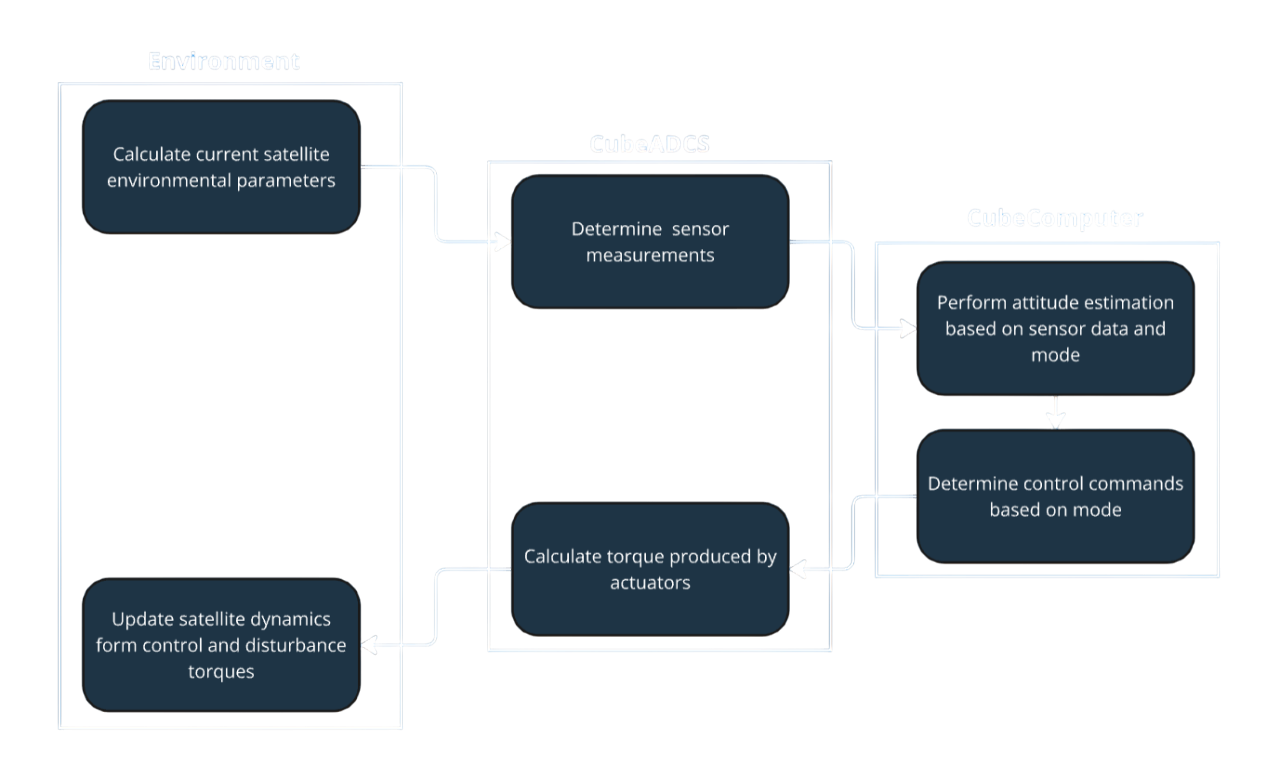 Figure 1: Flow diagram of the sequence of processes simulated each iteration when utilizing the CubeSpace plugin
The attitude estimation and control step is performed by executing the same code that the CubeADCS flight computer will execute. For the reference implementation of the simulation, all the execution occurs on the PC that is running the simulator.
Hardware-In-the-Loop (HIL) simulations are conducted by substituting the CubeComputer reference model with a HIL-enabled CubeComputer which adds a communication interface to the CubeADCS CubeComputer as shown in Figure 2. The difference between the reference and HIL simulation, is that the estimation and control processing now takes place on the actual CubeADCS hardware. HIL simulations are described in more detail in the Hardware in the loop page.
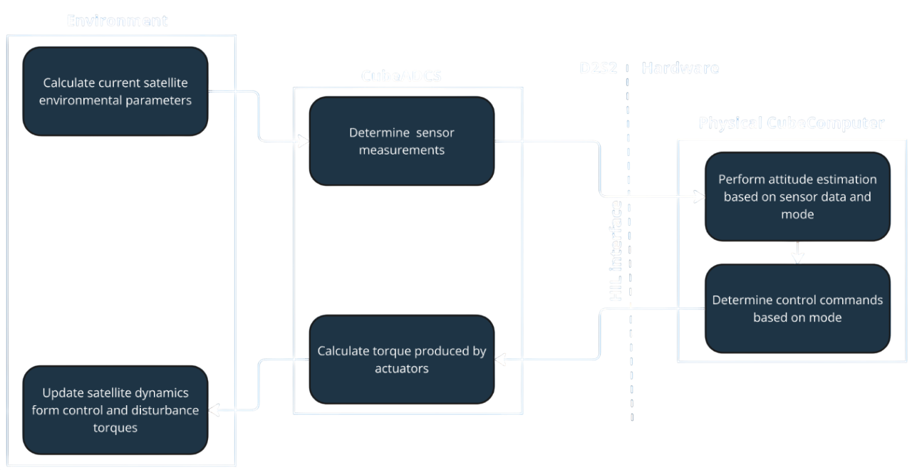 Figure 2: Flow diagram of the sequence of processes simulated each iteration when utilizing the CubeSpace plugin for HIL testing
DawnDusk ("we," "our," or "us") is committed to protecting your privacy. This Privacy Policy explains how your personal information is collected, used, and disclosed by DawnDusk. This Privacy Policy applies to our website, dawndusk.space , and its associated subdomains (collectively, our "Service"). By accessing or using our Service, you signify that you have read, understood, and agree to our collection, storage, use, and disclosure of your personal information as described in this Privacy Policy and our Terms of Service.
To help explain things as clearly as possible in this Privacy Policy, every time any of these terms are referenced, are strictly defined as:
We collect information from you when you visit our service, register, place an order, subscribe to our newsletter, respond to a survey or fill out a form.
Any of the information we collect from you may be used in one of the following ways:
We receive some information from the third parties when you contact us. For example, when you submit your email address to us to show interest in becoming our customer, we receive information from a third party that provides automated fraud detection services to us. We also occasionally collect information that is made publicly available on social media websites. You can control how much of your information social media websites make public by visiting these websites and changing your privacy settings.
We may share the information that we collect, both personal and non-personal, with third parties such as advertisers, contest sponsors, promotional and marketing partners, and others who provide our content or whose products or services we think may interest you. We may also share it with our current and future affiliated companies and business partners, and if we are involved in a merger, asset sale or other business reorganization, we may also share or transfer your personal and non-personal information to our successors-in-interest.
We may engage trusted third party service providers to perform functions and provide services to us, such as hosting and maintaining our servers and our service, database storage and management, e-mail management, storage marketing, credit card processing, customer service and fulfilling orders for products and services you may purchase through our service. We will likely share your personal information, and possibly some non-personal information, with these third parties to enable them to perform these services for us and for you.
We may share portions of our log file data, including IP addresses, for analytics purposes with third parties such as web analytics partners, application developers, and ad networks. If your IP address is shared, it may be used to estimate general location and other technographics such as connection speed, whether you have visited the service in a shared location, and type of device used to visit the service. They may aggregate information about our advertising and what you see on the service and then provide auditing, research and reporting for us and our advertisers.
We may also disclose personal and non-personal information about you to government or law enforcement officials or private parties as we, in our sole discretion, believe necessary or appropriate in order to respond to claims, legal process (including subpoenas), to protect our rights and interests or those of a third party, the safety of the public or any person, to prevent or stop any illegal, unethical, or legally actionable activity, or to otherwise comply with applicable court orders, laws, rules and regulations.
We will collect personal information that you submit to us. We may also receive personal information about you from third parties as described above.
By submitting your email address on our service, you agree to receive emails from us. You can cancel your participation in any of these email lists at any time by clicking on the opt-out link or other unsubscribe option that is included in the respective email. We only send emails to people who have authorized us to contact them, either directly, or through a third party. We do not send unsolicited commercial emails, because we hate spam as much as you do. By submitting your email address, you also agree to allow us to use your email address for customer audience targeting on sites like Facebook, where we display custom advertising to specific people who have opted-in to receive communications from us. Email addresses submitted only through the order processing page will be used for the sole purpose of sending you information and updates pertaining to your order. If, however, you have provided the same email to us through another method, we may use it for any of the purposes stated in this Policy. Note: If at any time you would like to unsubscribe from receiving future emails, we include detailed unsubscribe instructions at the bottom of each email.
We are incorporated in SOUTH AFRICA. Information collected via our website, through direct interactions with you, or from use of our help services may be transferred from time to time to our offices or personnel, or to third parties, located throughout the world, and may be viewed and hosted anywhere in the world, including countries that may not have laws of general applicability regulating the use and transfer of such data. To the fullest extent allowed by applicable law, by using any of the above, you voluntarily consent to the trans- border transfer and hosting of such information.
We take precautions to protect the security of your information. We have physical, electronic, and managerial procedures to help safeguard, prevent unauthorized access, maintain data security, and correctly use your information. However, neither people nor security systems are foolproof, including encryption systems. In addition, people can commit intentional crimes, make mistakes or fail to follow policies. Therefore, while we use reasonable efforts to protect your personal information, we cannot guarantee its absolute security. If applicable law imposes any non-disclaimable duty to protect your personal information, you agree that intentional misconduct will be the standards used to measure our compliance with that duty.
The rights you have to request updates or corrections to the information we collect depend on your relationship with us. Personnel may update or correct their information as detailed in our internal company employment policies. Customers have the right to request the restriction of certain uses and disclosures of personally identifiable information as follows. You can contact us in order to (1) update or correct your personally identifiable information, (2) change your preferences with respect to communications and other information you receive from us, or (3) delete the personally identifiable information maintained about you on our systems (subject to the following paragraph), by cancelling your account. Such updates, corrections, changes and deletions will have no effect on other information that we maintain, or information that we have provided to third parties in accordance with this Privacy Policy prior to such update, correction, change or deletion. To protect your privacy and security, we may take reasonable steps (such as requesting a unique password) to verify your identity before granting you profile access or making corrections. You are responsible for maintaining the secrecy of your unique password and account information at all times. You should be aware that it is not technologically possible to remove each and every record of the information you have provided to us from our system. The need to back up our systems to protect information from inadvertent loss means that a copy of your information may exist in a non-erasable form that will be difficult or impossible for us to locate. Promptly after receiving your request, all personal information stored in databases we actively use, and other readily searchable media will be updated, corrected, changed or deleted, as appropriate, as soon as and to the extent reasonably and technically practicable. If you are an end user and wish to update, delete, or receive any information we have about you, you may do so by contacting the organization of which you are a customer.
If you are one of our workers or applicants, we collect information you voluntarily provide to us. We use the information collected for Human Resources purposes in order to administer benefits to workers and screen applicants. You may contact us in order to (1) update or correct your information, (2) change your preferences with respect to communications and other information you receive from us, or (3) receive a record of the information we have relating to you. Such updates, corrections, changes and deletions will have no effect on other information that we maintain, or information that we have provided to third parties in accordance with this Privacy Policy prior to such update, correction, change or deletion.
We reserve the right to transfer information to a third party in the event of a sale, merger or other transfer of all or substantially all of the assets of us or any of its Corporate Affiliates (as defined herein), or that portion of us or any of its Corporate Affiliates to which the Service relates, or in the event that we discontinue our business or file a petition or have filed against us a petition in bankruptcy, reorganization or similar proceeding, provided that the third party agrees to adhere to the terms of this Privacy Policy.
We may disclose information (including personal information) about you to our Corporate Affiliates. For purposes of this Privacy Policy, "Corporate Affiliate" means any person or entity which directly or indirectly controls, is controlled by or is under common control with us, whether by ownership or otherwise. Any information relating to you that we provide to our Corporate Affiliates will be treated by those Corporate Affiliates in accordance with the terms of this Privacy Policy.
We keep your information only so long as we need it to provide service to you and fulfill the purposes described in this policy. This is also the case for anyone that we share your information with and who carries out services on our behalf. When we no longer need to use your information and there is no need for us to keep it to comply with our legal or regulatory obligations, we'll either remove it from our systems or depersonalize it so that we can't identify you.
We implement a variety of security measures to maintain the safety of your personal information when you place an order or enter, submit, or access your personal information. We offer the use of a secure server. All supplied sensitive/credit information is transmitted via Secure Socket Layer (SSL) technology and then encrypted into our Payment gateway providers database only to be accessible by those authorized with special access rights to such systems, and are required to keep the information confidential. After a transaction, your private information (credit cards, social security numbers, financials, etc.) is never kept on file. We cannot, however, ensure or warrant the absolute security of any information you transmit to us or guarantee that your information on the Service may not be accessed, disclosed, altered, or destroyed by a breach of any of our physical, technical, or managerial safeguards.
The laws of SOUTH AFRICA, excluding its conflicts of law rules, shall govern this Agreement and your use of our service. Your use of our service may also be subject to other local, state, national, or international laws.
By using our service, registering an account, or making a purchase, you consent to this Privacy Policy.
This Privacy Policy applies only to the Services. The Services may contain links to other websites not operated or controlled by us. We are not responsible for the content, accuracy or opinions expressed in such websites, and such websites are not investigated, monitored or checked for accuracy or completeness by us. Please remember that when you use a link to go from the Services to another website, our Privacy Policy is no longer in effect. Your browsing and interaction on any other website, including those that have a link on our platform, is subject to that website's own rules and policies. Such third parties may use their own cookies or other methods to collect information about you.
We use "Cookies" to identify the areas of our website that you have visited. A Cookie is a small piece of data stored on your computer or mobile device by your web browser. We use Cookies to personalize the Content that you see on our website. Most web browsers can be set to disable the use of Cookies. However, if you disable Cookies, you may not be able to access functionality on our website correctly or at all. We never place Personally Identifiable Information in Cookies.
If we decide to change our privacy policy, we will post those changes on this page, and/or update the Privacy Policy modification date below.
We may display, include or make available third-party content (including data, information, applications and other products services) or provide links to third-party websites or services ("Third- Party Services").
You acknowledge and agree that we shall not be responsible for any Third-Party Services, including their accuracy, completeness, timeliness, validity, copyright compliance, legality, decency, quality or any other aspect thereof. We do not assume and shall not have any liability or responsibility to you or any other person or entity for any Third-Party Services.
Third-Party Services and links thereto are provided solely as a convenience to you and you access and use them entirely at your own risk and subject to such third parties' terms and conditions.
Cookies
We use Cookies to enhance the performance and functionality of our
service but are non-essential to their use. However, without these
cookies, certain functionality like videos may become unavailable or
you would be required to enter your login details every time you visit
our service as we would not be able to remember that you had logged in
previously.
Local Storage Local Storage sometimes known as DOM storage, provides web apps with methods and protocols for storing client-side data. Web storage supports persistent data storage, similar to cookies but with a greatly enhanced capacity and no information stored in the HTTP request header.
Don't hesitate to contact us if you have any questions.
Via Email: info@dawndusk.space