 menu
menu
A CubeADCS HIL simulation involves connecting the simulator to a physical CubeADCS, and letting the remote ADCS perform the estimation and control processing. This uses the same hardware setup as when interfacing the CubeADCS to the CubeSupport application.
In a simulation where a CubeADCS is being simulated, the HIL interaction is achieved by a CubeComputer(HIL) model object which communicates with a physical CubeComputer using a hardware interface.
It is necessary that the user understands the CubeADCS functions and operations, and also knows how to command the ADCS through the CubeSupport app. The relevant reference documentation can be found at the bottom of this page.
It is possible to perform a HIL simulation where the reaction wheels and magnetorquers connected to the CubeComputer in the ADCS unit are active and follow the control commands to match with the simulation. For this, the reaction wheels and CubeControl Signal must be switched on before connecting to the simulator. The Activate Actuators setting for the CubeComputer(HIL) must also be set to true.
In absence of a connection the satellite will simply propagate its attitude with no control signals.
A CubeADCS HIL simulation is enabled by changing the CubeComputer reference model in the simulation scenario to a HIL-enabled CubeComputer5. (Or, for Gen1, the HIL-enabled CubeComputer4.)
To avoid having to recreate the entire simulation model, a script that performs the above substitution is included in the CubeSpace plugin for D2S2. The HIL Setup script will exchange the reference CubeComputer model in the currently loaded scenario with the HIL counterpart.
For Gen2 HIL simulations, either a FTDI USB/UART cable, or PCAN USB interface is required to connect the computer D2S2 is running on to the CubeADCS. The option (UART, CAN) can be selected from the CubeComputer(HIL) model object's Interface input property depending on the selected hadware.
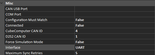
Figure 1: Gen2 CubeComputer properties, showing HIL connection options
Should the user need to use the CubeSupport during the HIL testing, this can be achieved by interfacing to the CubeComputer via both the FTDI USB/UART cable and PCAN USB. As long as the CubeSupport app and D2S2 is not using the same hardware, the setup should execute successfully.
For UART connections, the COM port may be specified prior to connecting, to match with the port where the USB/UART interface is plugged in. The COM Port setting may also be left open, in which case the connect action will iterate through all available COM ports until a CubeADCS is found.
Only the CubeSpace communications protocol is supported for CAN connections. When connecting using CAN, the CAN ID of the remote CubeComputer must be known. This is specified in the CubeComputer CAN ID property in Figure 1 and can be found using the CubeSupport app. Additionally the source CAN ID (with which D2S2 will identify itself) must be specified in the D2S2 CAN ID property. See Figure 1 as reference.
The HUB connection option is a method to interface to the CubeADCS that requires special interfacing hardware. This is feature is still in development.
Once the abovementioned conditions are met, ensure the CubeComputer is ready to establish a connection. The following conditions must be checked:
If everything is in order, the HIL simulation can be connected to the CubeComputer by toggling the Connect input property of the Gen2 CubeComputer inputs. If no errors are displayed, the connection is successfull and the simulation can be run.
It might take a few seconds for the connection to be made. In the background, the simulator exchanges a number of telecommands or telemetries with the CubeADCS. This includes the following exchanges:
The same exchange will occur every time the simulation is reset.
In a HIL simulation, the ADCS task in the CubeComputer control program runs as normal, and the simulator synchronises itself to the control program.The control program will perform the same processing and communication to nodes as in real operation. If the actuators are connected to the CubeADCS and powered on, the wheels will spin up to the wheel speeds corresponding to the simulation values, and the magnetorquers will fire likewise.
If the simulator loses synchronisation with the control program, it will repeat the same simulation iteration, up to a maximum number of retries specified by the Maximum Sync Retries property. If synchronisation fails past this point, an error will be displayed, and the simulation will stop. Figure 2 presentes a flow diagram of the HIL sequence.
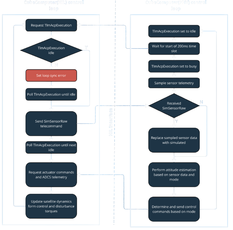 Figure 2: Flow diagram of the sequence of processes simulated each iteration during HIL testing
The CubeComputer(HIL) model object will also report additional states to reflect the remote CubeComputer state.
| Model State Property | Description | Possible Values |
|---|---|---|
| HIL Interface | --- | --- |
| AdcsUpdateTime | Time that it takes for the simulator to synchronise to the remote CubeComputer plus the time it takes to perform communication. This value equals Sync1Time + Sync2Time + CommsTime | duration[s] |
| CommsTime | Time that it takes for communication between simulator and remote CubeComputer to conclude | duration[s] |
| D2s2UpdateTime | Time that it takes for the simulator's internal update (propagating satellite state, calculating sensor measurements) | duration[s] |
| HilUpdateMissed | Indication that the remote CubeComputer performed one iteration of the control loop, without simulator measurements | True or false |
| IsConnected | Indicates if the HIL connection has been established | True or false |
| LoopTimeDelta | Time inbetween simulation update iterations | duration[s] |
| RetryNeeded | Indicates if a simulation iteration had to be retried (either as a result of synchronisation error, or telecommand/telemetry error) | True or false |
| Sync1Time | Time that it takes for the remote CubeComputer to go from idle to busy state | duration[s] |
| Sync2Time | Time that it takes for the remote CubeComputer to go from busy to idle state | duration[s] |
| SyncError | Indicates that the remote CubeComputer did not change between busy and idle states in the expected way (or with expected timeout durations) | True or false |
HIL simulation is also possible using the CubeSpace Gen 1 hardware.
For Gen1 HIL simulations, an FTDI USB/UART cable is required, connected to the CubeADCS. The CubeADCS must be powered on and running the CubeACP application. The system configuration of the CubeACP must match with the configuration in the scenario file (wheel sizes must match, magnetorquer properties must match etc.)
The hardware connection is established by changing the Connected property of the CubeComputer(HIL) model object to true.
The CubeComputer(HIL) model object will report states to reflect the connected CubeADCS state:
| Model State Property | Description | Possible Values |
|---|---|---|
| ACP State | --- | --- |
| AdcsState | Current ADCS Run mode | AdcsOff, AdcsEnabled, AdcsSimulation |
| ControlModeState | Current ADCS control mode | Any of the control modes listed in the CubeADCS Firmware Reference Manual |
| EstimationModeState | Current ADCS estimation mode | Any of the estimation modes listed in the CubeADCS Firmware Reference Manual |
| ControlModeChangeNotAllowed | Status flag in ADCS state telemetry, to indicate if commanded control mode was not allowed | True or False |
| EstimatorChangeNotAllowed | Status flag in ADCS state telemetry, to indicate if commanded estimation mode was not allowed | True or False |
| HIL Setup | --- | --- |
| Is Remote ADCS connected | Flag to indicate if remote CubeACP is connected | True or False |
It is useful for the simulator to be used in a HIL setup where the CubeADCS is commanded from an OBC (On-board Computer). This allows for verification of mission stages and operational scenarios. The OBC will typically command the CubeADCS in such a setup, to change modes and request periodic telemetry for logging. The control mode changes will cause the CubeADCS to react as if in flight, and the telemetry that is returned will be similar to what will be observed in flight.
Gen1 ADCS can only connect to the simulator through UART. The I2C or CAN (if populated) interface is available to the OBC. Gen2 ADCS can use any of the available communications interfaces to the OBC after the HIL interface is connected.
Although it is still possible to change control and estimation modes and set ADCS configuration and reference commands through the D2S2 graphical user interface in such a setup, it is logical that the OBC would perform such commanding instead. The D2S2 model object for the HIL CubeComputer will report the control and estimation modes that are currently used on the remote CubeADCS, regardless of which entity commanded the state change.
If you are running into issues, feel free to contact support@cubespace.co.za for assistance. To minimize troubleshooting time, however, please check the following common issues:
A common issue that may oocur is a large enough mismatch in UNIX time between the D2S2 scenario and the orbit parameters for the CubeComputer. When the connection is established, one of the first commands sent to the CubeComputer is intended to set the orbit parameters on the remote ADCS to match with the scenario. Users will, however, experience a TC ID 68 NACK error if the orbit epoch (in the orbit parameters) and scenario start time differs by more than two weeks. This is a safety feature built into the CubeComputer to prevent incorrent orbit parameters from being uploaded during flight. It can be fixed by updating the simulation Start Epoch in Simulation Settings to match with the epoch in the orbit parameters.
If the scenario fails with the prompt "Error initializing scenario", it may be because the CubeSpace plugin is not loaded. Please ensure your license supports the plugin and that it is loaded.
Communication errors may be attributed to outdated firmware on the CubeComputer. Please ensure you are using the most up to date software.
Many of the control modes and of course the magnetorquers are reliant on the presence of a magnetic field in the scenario. If the magnetic field is not present, the satellite ADCS will not perform as well as expected.
This is an outdated function and is soon to be depricated. Enableling this parameter may cause the ADCS to not perform as well as expected.
If you are experiencing syncing errors and you are using UART communication to interface between the CubeComputer and D2S2, please consider reducing the latency timer on the COM port utilized for this operation. The COM port latency is adjusted in from the Windows device manager as seen in Figure 3 below.
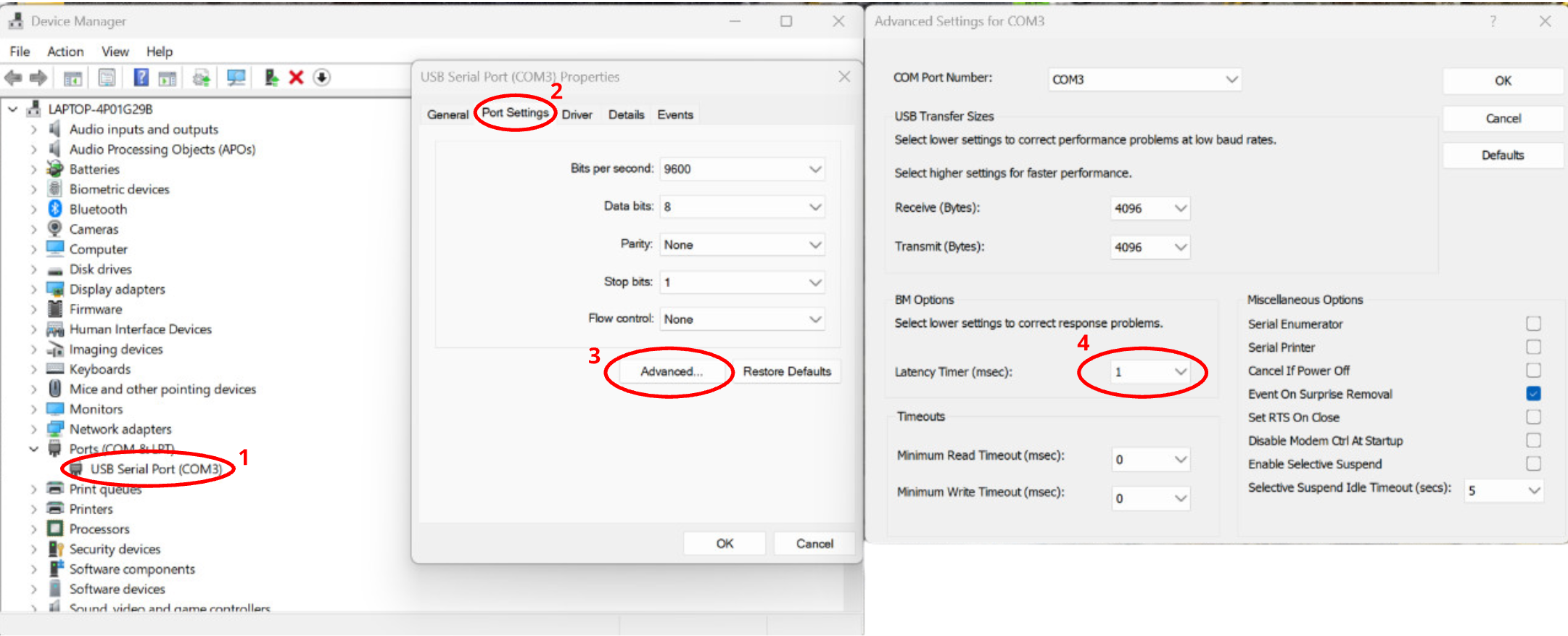 Figure 3: Adjusting the latency of the COM port through Windows device manager.
Are you sure you followed all the checks in this page? Maybe read through it one more time just to be sure.
Many issues faced when setting up the D2S2 HIL interface comes from a lack of understanding of CubeSpace ADCS products. Users are reccommended to become familiar with the following documentation before utilizing the D2S2 HIL functionality:
If you do not have access to this documentation and you are a CubeSpace client, please contact support@cubespace.co.za for assistance.